Ten seconds to know whether a MEMS accelerometer really works
A bench and firmware that say yes or no on whether a MEMS accelerometer is present and well coupled to the structure, even in the hands of a non-specialist operator and with the machine running.
- > 40 dB
- signal-to-noise ratio in every configuration
- ~10 s
- test duration, with a yes/no result
- 23 dB
- margin on the acceptance threshold
The context
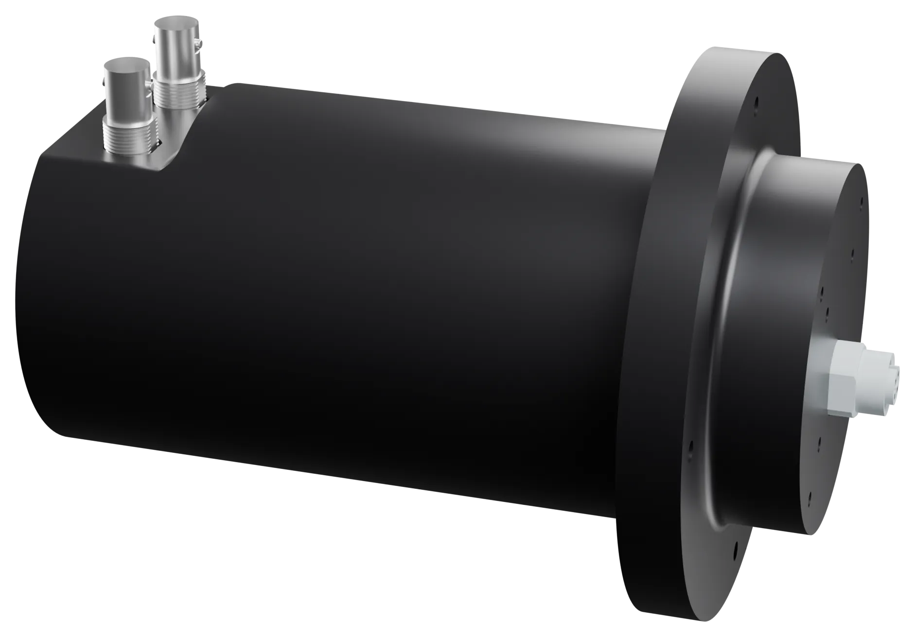
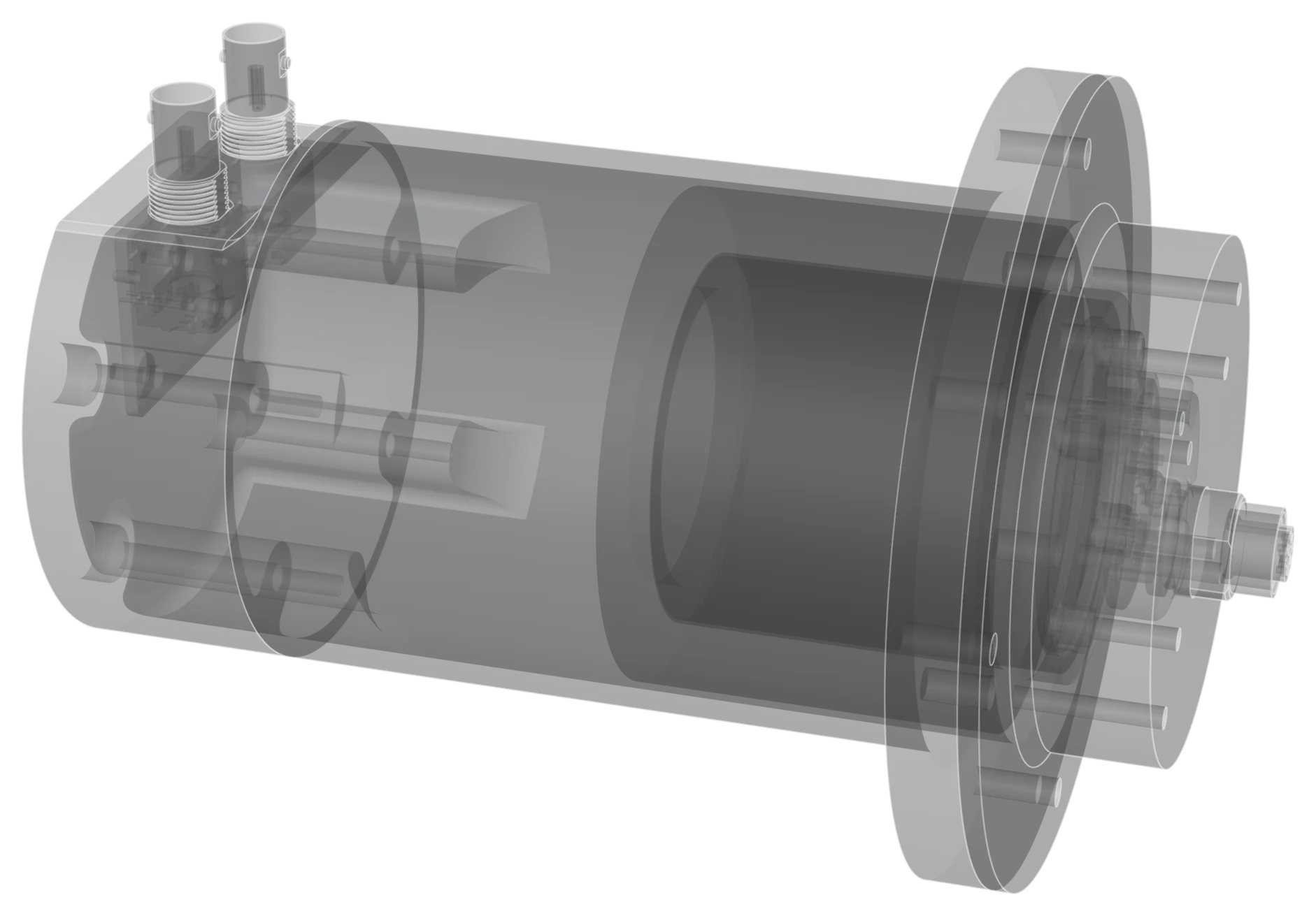
The client installs MEMS accelerometers on structures that differ from one another. After installation a simple confirmation is needed: is the accelerometer there, does it work, is it firmly attached to the structure? Whoever runs the check is not a measurement specialist, and the test must give a yes or no in a few seconds. The structures are part of mission-critical systems: a poorly attached accelerometer must not pass the check.
The problem
An accelerometer that is “alive” but badly attached still returns data: the defect is invisible by eye. Moreover, every structure has its own resonances, and background noise in an industrial environment can easily drown a weak test signal.
Technical choices, and why
Pure-tone excitation instead of broadband. With a tone at a known frequency, all the test energy is where we look for it, so little power is enough to rise above the noise.
Frequencies chosen through modal analysis. Before fixing the tones we studied the resonances of the test structure with automated sweeps and chirps. The tones fall away from resonances, so the response depends on how the accelerometer is coupled, not on the shape of the structure.
Lock-in detection on the microcontroller. The firmware multiplies the accelerometer signal by a reference at the tone frequency and averages it: everything not at the test frequency, machine noise included, cancels out.
A double threshold: amplitude and signal-to-noise ratio. A badly attached accelerometer responds more weakly, a faulty one responds with noise. With both thresholds we catch both cases.
Two phases. A one-off calibration for each type of structure, then the ten-second operational test, always the same for the operator.
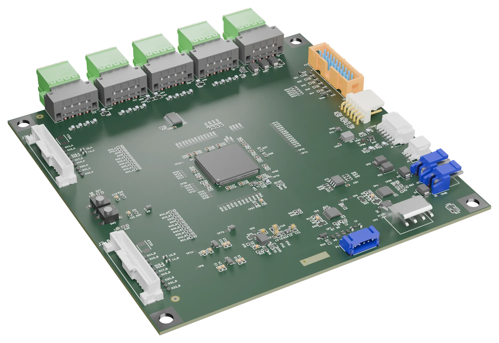
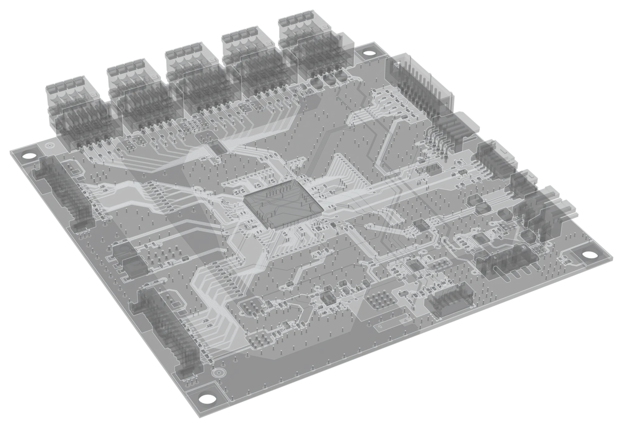
Two accelerometers read in parallel over SPI, with FIFO and double buffering, without losing samples.
How we verified it
- Automated sweeps and chirps with a generator and oscilloscope driven over SCPI.
- Monte Carlo simulation to measure noise robustness: the test stays reliable up to 19 mg of added noise, against 1–10 mg typical of an industrial environment.
- Operator software with self-test and automated tests.
The result
Signal-to-noise ratio above 40 dB in every configuration tested, a test of about 10 seconds with a yes/no result and a 23 dB margin on the acceptance threshold.
What we bring to your projects
Signal processing on the microcontroller, test bench design, measurement automation and tests designed for the people who run them every day.