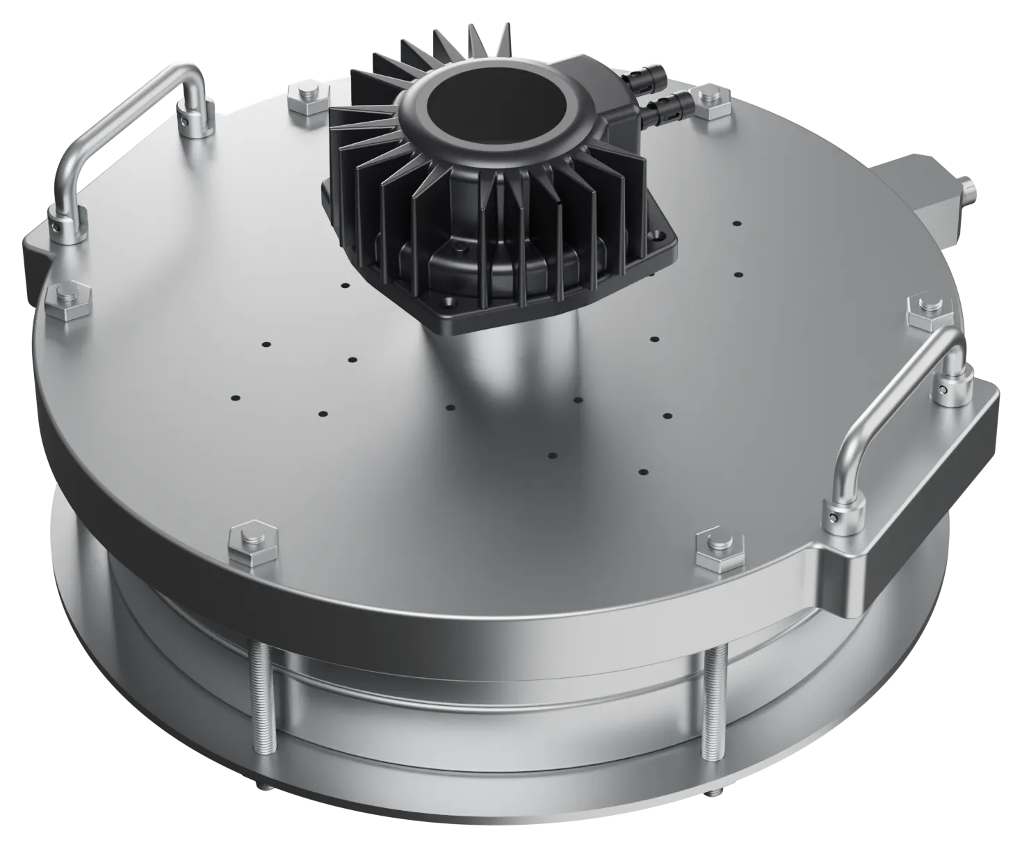
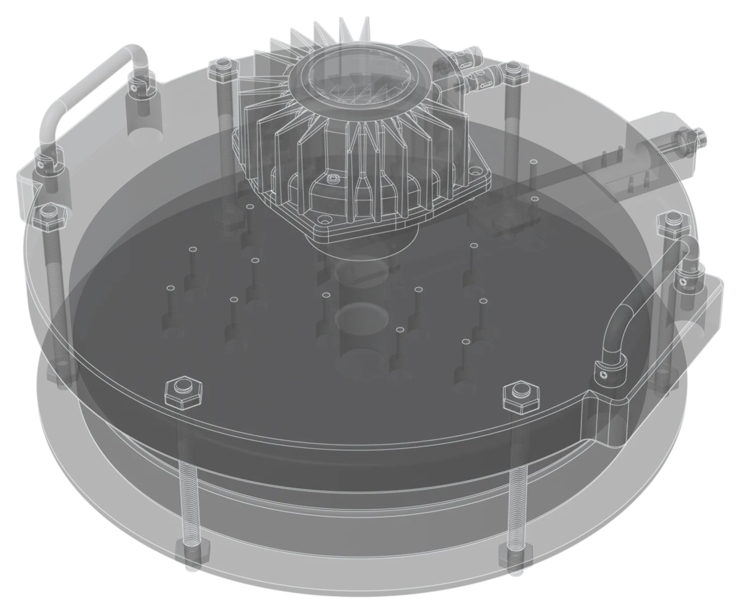
The test method would not have worked. We found out before building it
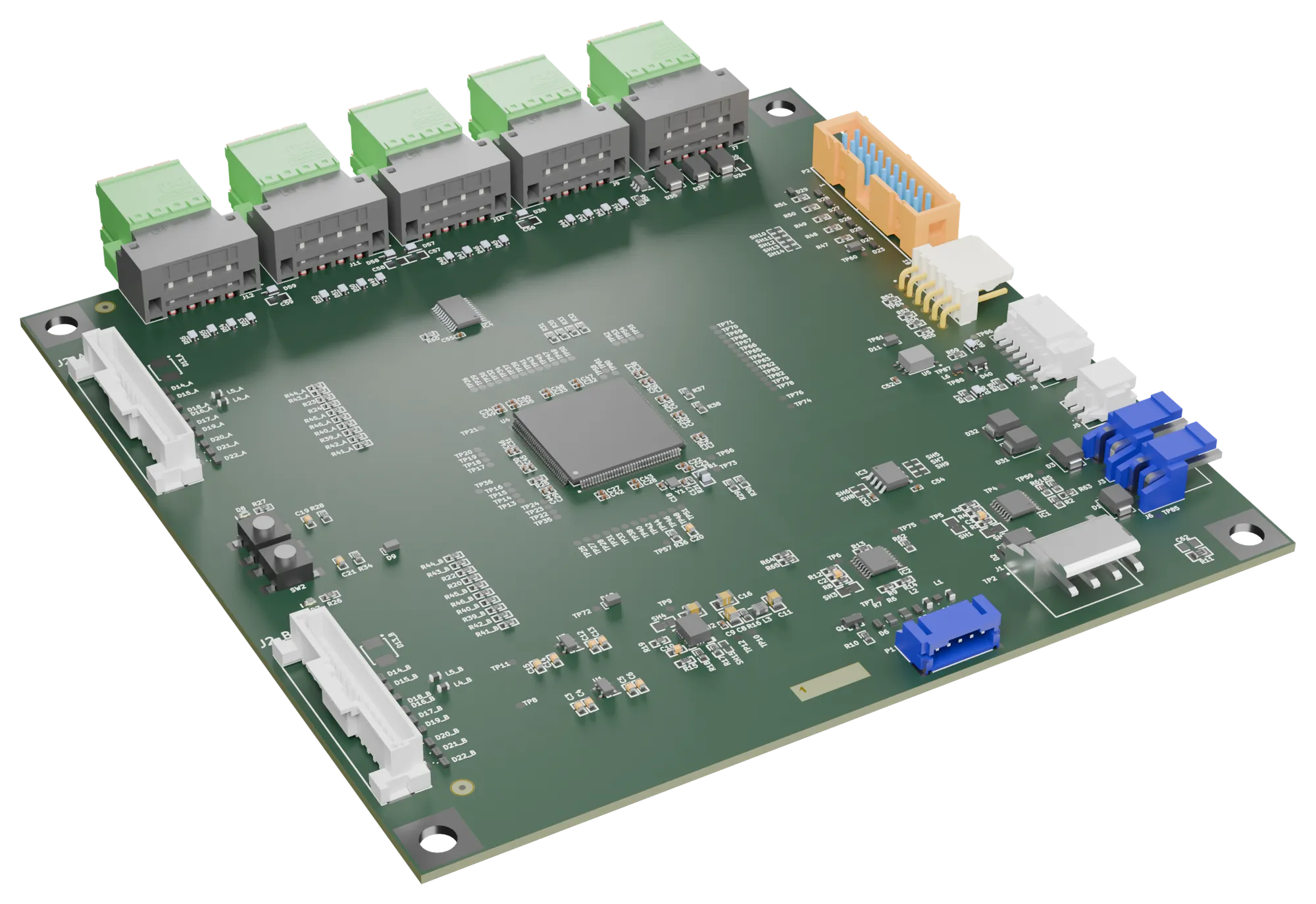
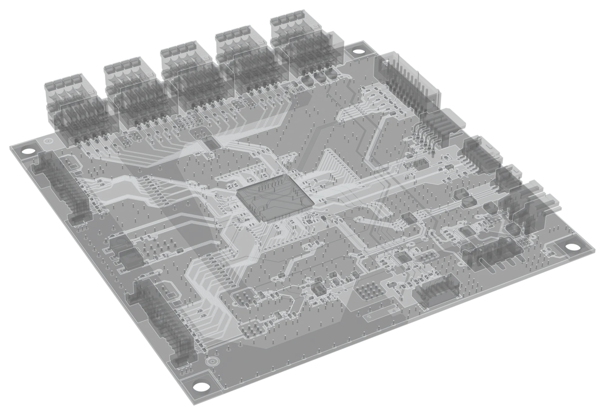
A bench that tells in seconds whether an electric-field sensor works, measuring capacitances of a few picofarads in air. The method planned at the start was ruled out with measurements, before any money went into hardware.
- ~1.4%
- estimated accuracy without calibration (requirement: 4.2%)
- ≤ 10 fF
- estimated resolution (requirement: 50 fF)
- 42%
- margin on the acceptance threshold
The context
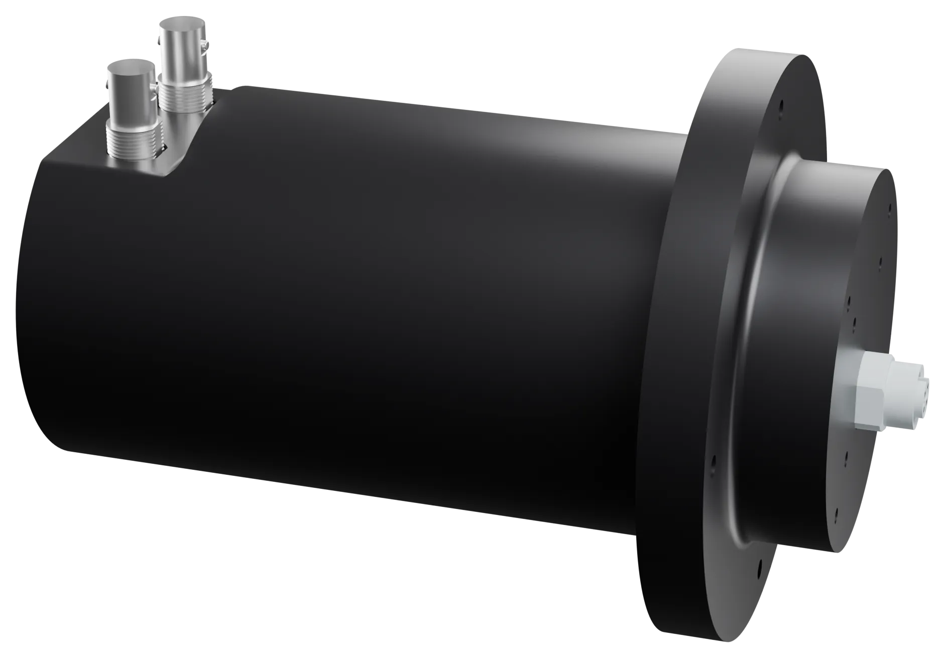
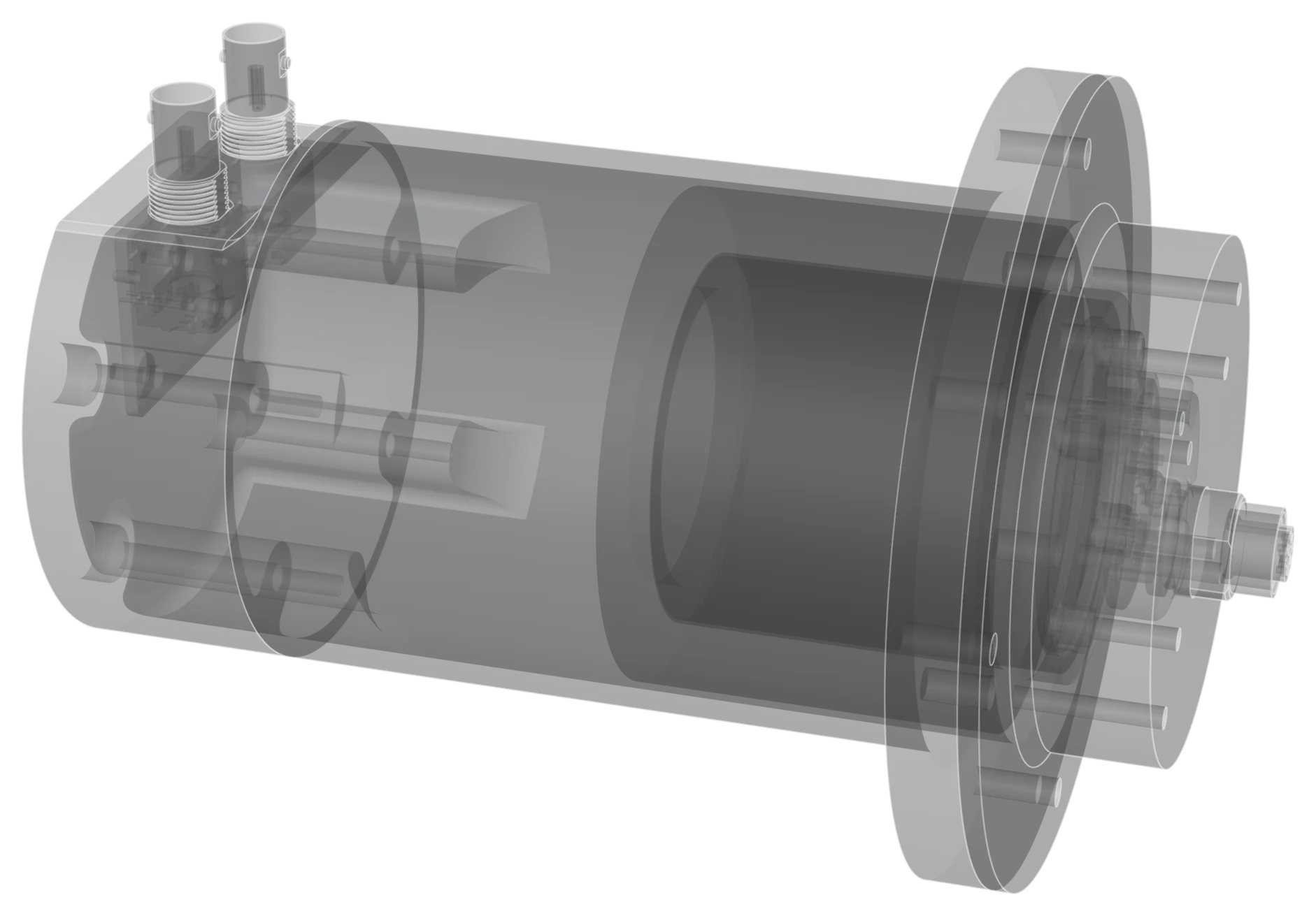
The client makes an electric-field sensor that operates under water. Production needed a fast test to tell whether each sensor works, without immersing it and without relying on the final product’s electronics. In air, though, the quantities involved are tiny: capacitances of a few picofarads. The sensor goes into a mission-critical system, so the bench had to meet tight tolerances.
The problem
The method in the initial proposal looked reasonable on paper: use the existing measurement chain and compare the response with a threshold. Before designing any board we ran a measurement campaign with commercial instruments, built a circuit model of the sensor and analysed its failure modes.
The result was clear: that method would not reliably tell a good sensor from a faulty one. The cable’s parasitic capacitance was of the same order as the signal to be measured. We told the client straight away, with the data.
Technical choices, and why
An auto-balancing bridge with a transimpedance amplifier. The same architecture as lab LCR meters: it holds the sensor at virtual ground and measures the current flowing through it. For capacitances this small it is far more stable than a charge amplifier.
Triaxial cable with active guard. The middle shield is driven at the same voltage as the centre conductor, so the cable capacitance carries no current and disappears from the measurement. This is what makes picofarad measurements repeatable.
I/Q demodulation. Separating the in-phase and quadrature components distinguishes capacitance from losses: a faulty sensor changes not only “how much” it reads but also “how”.
Signal generation on the microcontroller. A DDS on the STM32U5, with polyphase interpolation computed by the FMAC hardware accelerator, produces a clean sine at several frequencies with no external generator and no CPU load.
Multi-frequency measurement. Capacitance is estimated at several frequencies and compared: a defect also shows in how the response changes with frequency.
How we verified it
- SPICE simulation of the front-end before layout.
- Measurement campaigns with lab instruments driven over SCPI, to compare method and prototype repeatably.
- Desktop software with automated tests on the data processing.
The result
Performance estimated from circuit analysis: about 1.4% accuracy without calibration against a 4.2% requirement, and a resolution of 10 fF or better against the 50 fF required, with a 42% margin on the acceptance threshold.
The biggest value came at the start: the client invested in a method that works, instead of finding out in production that the test could not tell good parts from faulty ones.
What we bring to your projects
Analog measurement front-ends, signal processing on the microcontroller, automated test benches, and the habit of checking an idea with measurements before building it.